I am very interested in shader programming, which is likely due to my academic background in mathematical modelling and simulation. I wrote this small primer as a means to help provide an insight into shaders and light simulation to fellow course colleagues who wanted to know more.
What is VFX? How is it achieved?
Lighting
At the heart of all image perception, whether it be simulated or real, is light. Light is said to have the properties of a wave or the properties of individual particles (photons). But more saliently for graphics rendering it has the following properties:
- Light may be reflected
- It may be absorbed
- It may transmit and be refracted through a surface
- It may diffract through narrow apertures.
The first three properties are commonly simulated as their effects are more noticeable. Lighting is simply achieved by adding the light colour (comprising of individual red, green and blue components as in reality) to the pixel colour of a surface. Crucially however, light is not a perceivable wave or stream of photons, instead it is a vector in which the surface colour of geometries may change depending on their orientation to the light. The source of the light is not illuminated like in a bulb, and it will not produce a glow: this is a post effect called bloom, which is superimposed onto a light, averages the glow colour with nearby pixels and decays according to a function of distance. Four types of lights are available for rendering: directional lights, which have an orientation but no position and so translation is ineffective (often used for global scene lighting e.g., the sun); point or spherical lights, which have position and their lighting to an object decays with distance; spot lights for lighting in a specific direction from a single source; and ambient lights, which provide a uniform lighting colour value for all objects in a scene.
There is a dichotomy between local and global illumination models. Unlike the former the latter takes into account the contribution of light reflected off surfaces into a scene and the resulting cost in energy. Ray tracing and physical based lighting are global methods. Global illumination is described by an integral equation known as the rendering equation (https://en.wikipedia.org/wiki/Rendering_equation) which contains a function for incoming light and a bidirectional reflectance distribution function (BRDF), examples of which will be described below.
Graphics programming in general
It would be imprudent to describe graphical visual effects without giving a brief description of the other processes that are occurring whilst a scene is being rendered to the screen. Fletcher and Parberry (2015) describe nine processes in the pipeline. Briefly, these are:
1) Setting the scene, where the camera is positioned, light and fog options are set and the z-buffer is prepared;
2) Visibility determination, where objects visible to the camera are selected for rendering;
3) Setting object-level rendering states, where properties such as texture maps are installed into the rendering context;
4) Geometry generation, where geometry (commonly clusters of triangles), level of detail (LOD) or procedural rendering is submitted to the API;
5) Transformation and lighting, where vertex positions are transformed into camera space for projection and vertex-level lighting is calculated;
6) Backface culling and clipping, where ‘back-facing’ triangles and vertices outside of the view frustrum are culled from rendering;
7) Screen space projection, the 3D vertex information is projected onto the 2D screen space of the view device;
8) Rasterisation, where the pixels for rendering are selected and their shading parameters are extracted;
9) Pixel shading, where the output colour for the pixels within our rendered geometry is determined.
In the past, the aforementioned processes would occur only on the CPU. However, after the introduction of graphics hardware, the most expensive process of rasterisation was accomplished by the new hardware, which brings us to today, where GPU’s may now oversee all rendering processes. Gregory (2014) describes this pipeline. In brief this pipeline encompasses:
- Vertex Shading, including the processes described in point 5 above
- Geometry shading
- Stream output, where previously processed data may be fed back into the pipeline for further processing. Processed data from hair physics simulation is an example of data that can be fed back into the vertex shading stage
- Clipping, see point 6 above
- Screen mapping, see point 7 above
- Triangle set up and traversal stages within rasterisation (point 8 above)
- Early z-test, in the past depth testing for occluded geometry was performed in the final stage, however it may be performed as an early test
- Pixel shading, see point 9 above
- Merging/blending raster operations stage. This encompasses the depth test for occluding, the alpha test, for transparency, commonly achieved by calculating a weighted average between the colours of two superimposed pixels, and the stencil test, for shadow rendering.
The output of the GPU pipeline is the frame buffer, containing the pixels specifically from solid three dimensional geometries, to be rendered onto the screen. The frame buffer may alternate with another buffer, this is called double buffering to allow complete rendering of a frame whilst the other is being processed. Crucially to this blog, certain stages in the GPU pipeline are now configurable, such as stage 9, whereas some are programmable. These are the vertex and pixel (or fragment) shading programs, and since DirectX 10, geometry shaders. These microprograms do not have access to memory directly, but apart from the memory supplied within texture maps they may access GPU registers (making certain programming paradigms such as if/else statements inefficient). In VFX, shaders are very important, however, manipulation of the frame buffer and overlaying the rendered scene, such as user interface graphics and particle effects. These are collectively named post-effects.
Shaders
Phong Lighting
One of the shader scripts I learned to write was using the Phong lighting model. It contains as BRDF’s ambient lighting , Lambertian diffuse lighting and Blinn specular lighting.

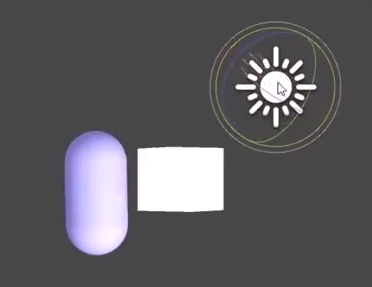
Ambient lighting represents a ubiquitous light source and averages the light colour with the material pixel colour (e.g., will make things whiter with white light). Diffuse lighting represents light scattering due to a rough surface, and averages the light colour with a more specific set of pixels depending on the orientation of the light (and position with point lights). Specular lighting represents light reflection of a smooth surface, from highlighting a more specific set of pixels according to their orientation with the light source (the ray of incidence) and the orientation of the reflected ray with the viewport, v:
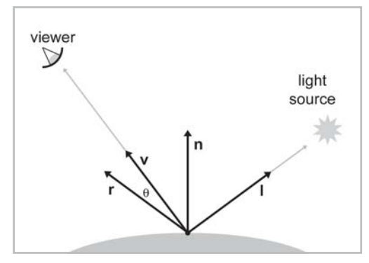
Where n is the normal of the vertex or pixel, I is the ray of incidence from the light source and r is the reflection vector. The highlighted patch of pixels prominent on smooth surfaces calculated by shader code using the Blinn lighting model is colloquially termed a ‘hotspot’. The reflection vector can be calculated as below:
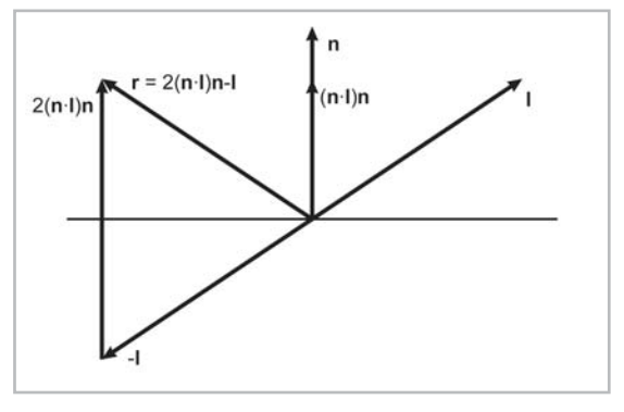
We arrive at the reflection vector projecting the incident ray onto the normal using a scaled dot product (n.I)n and then doubling this quantity. By subtracting this new vector from the incident vector we arrive at the reflection vector 2(n.i)n-I, pointing from I to 2(n.I)n. Remembering that vectors do not have a position this reflection vector is equal to the vector shown above. Alternatively by negating the incident vector to -I the reflection vector is also equal to the displacement from -I to 2(n.I)n as above. Note these vectors must be normalized. The shader code in CG that may be used to code for Phong lighting is below:
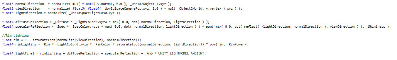
LightFinal is added to the material colour. The diffuse is simply a proportion of the light colour given by the dot product of the normal and light vector: the more parallel the vectors the brighter the light. The Blinn specular (above) is the dot product of the reflection and view vector, exponentiated to “shininess”. The higher the exponent, the lower the overall product is, and the smaller the hotspot becomes. Note these values are clamped to be above zero (using Max() ). Rim lighting is calculated in a similar way to specular, but as a reverse compliment of the cos(ϑ) between the view and normal vector.